Technical description of the electrostatic plate.
In the reference pattern, the electric field is produced in the holes of a grid in contact with the gas. The grid is the positive plate of a condenser and it is kept apart from the cathode by a thin dielectric layer ( diagram 20). The holes dimension is reduced as much as possible to avoid a breakdown in the gas which might occur because of the necessarily very high electric field.
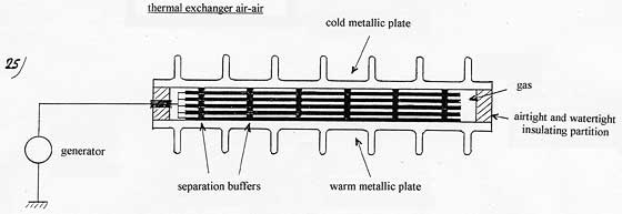
To get a difference of temperature important enough
between the cold and the warm source, the solution is to proceed by floors, that is to say to superpose the plates like in a millefeuille, the cold plate from a floor becoming the warm plate of the next floor.
A calculation of the electric power consumed
shows that it is negligible compared to the power of thermal transfer, with allows to expect a very high coefficient of performance ( C.O.P), which cannot be compared to Carnot’s.
Different possible configurations
are examined, the aim being to try to simplify the manufacturing, to reduce the cost, but also to optimize the power and the reliability, especially by trying to eliminate the risk of deterioration of the dielectric linked to the very high electric field.
|
|
It is a condenser whose plate, charged negatively is made of the metal plate on which is laid a thin dielectric and the grid, in contact with the gas which constitutes the positively charged armature. This grid could be made by engraving holes in a vacuum-packed metal layer, laid on the insulating material. The grid plays the role of the Faraday cage mentioned before in “Electrostatic principle”. It allows to generate a high field at the surface of the plate, more precisely in the holes of the grid as well as an insignificant residual field in the whole remaining gaseous space. |

Why don’t we apply the electric field to the whole gaseous space?
It would avoid the grid. But it is the gradient of the electric field in the space which induces the attraction of the gas molecules. It is between the area where the field is insignificant and the area where the field is high (in the holes of the grid) that they are attracted. In such a zone of variable field, the positive and negative electric charges of the molecular dipole don’t exactly undergo the same electrostatic force (attraction or repulsion) since they are not located at the same place. And it is this difference of force between the attraction of a charge and the repulsion of the opposite charge which induces a resultant of force which is strictly speaking the attraction force of the molecule. This force always exerts itself towards the field gradient, that is to say towards the high field and not according to the direction of the electric field.
If we put a gas into a uniform electric field, between a cathode and an anode, the gas molecule wouldn’t undergo any attraction force. Yet, each molecule would behave as a dipole because of the electric field which keep the opposite charges apart, but the electric field being uniform, the repulsion force of a charge would compensate exactly the attraction force of the opposite charge.
Here is a very enlightening experiment about this phenomenon. If we introduce a blade into a charged condenser, the blade is attracted into the condenser. The attraction energy comes from the polarization of the blade, that is to say from the induced charge on each surface of the blade when penetrating into the condenser. Those charges exert an attraction in relation to the positive and negative terminal of the condenser such as can be seen on the diagram below. The attraction force of the blade in the condenser is a resultant of all the forces and it persists as long as the blade isn’t totally introduced into the condenser. As soon as it is fully introduced, the attraction force disappears.
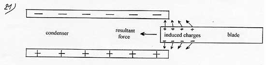
The principle is the same for a single particle. Such a particle would be attracted when penetrating into the condenser but not afterwards anymore. The attraction force is obvious in the case of the blade because of the very high number of molecules it contains.
Dimension of the grid
To avoid all risks of a gas breakdown within the zone of high field, that is to say in the holes of the grid, we must reduce to the minimum the size of those holes as well as the thickness of the grid. In the same way, we can only reduce the thickness of the dielectric in proportion to the holes of the grid. Yet, the thinner the dielectric is, the higher its resistance at breakdown (dielectric rigidity) is. The dielectric rigidity of a 5-micron layer of parylene would be satisfying to apply to the required electric field (250 KV/mm). But one may consider that those dimensions mustn’t be exceeded.
The gas pressure
One must see to it that the free mean path of an electron in the gas (without ionization) nearly corresponds to the distance between the plates in order to avoid the multiplication of the electrons which can be emitted by the dielectric surface which could produce a breakdown in the gas. In the case of a distance between the plates of 0.1 mm we would need a minimum vacuum of about 0.01 bar.
Value of the electric field and potential
The average value of the electric field on the surface is going to determine the molecules energy of attraction and the heating of the plate. This field is higher in the holes of the grid on the dielectric surface and much less on the horizontal metallic surface of the grid. According to some computer-made calculations, the average value of the electric field on the surface with a plastic dielectric whose Er = 2, would be about twice the electric field existing in the dielectric. A field of 250 KV / mm in the dielectric is thus necessary if we want to reach an average field of 500 KV /mm on the surface. With a dielectric thickness of 5 microns, the electric potential would rise to 1.25 KV. For an identical electric field, the necessary potential is all the more lower because the dielectric is thin.
Separation buffers
|
|
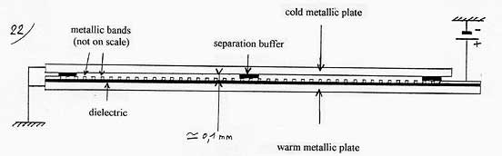
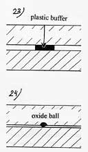
Spread over the whole surface of the plates, they maintain regular spaces between them. They are as very few and as narrow as possible in order to limit the return of heat the return of heat in the normal direction : warm plate => cold plate. A way to make them would consist in putting, on the inferior side of each plate (at the opposite of the graved side), an adhesive plastic layer with a thickness equal to the required separation then, in milling this layer away except for what we want to keep for the buffers. Another possibility allowing to reduce the distance of separation and then to rise the power of thermal transfer would consist in making oxide micro-balls on the surface of the metal, by ionic implantation for instance. |
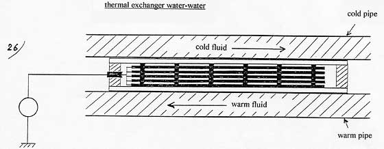
General configuration
A plate being a few degrees warmer than the opposite one, the heating must be multiplied to get a difference of temperature big enough between the cold source and the warm source. The solution consists in proceeding by stages, that is to say to superpose the plates, the cold plate of a stage becoming the warm plate of the following stage. If we take up again the example described in diagram 14, the power of thermal transfer of 1400 watts we had between two plates would be recovered but now between the cold source an the warm source, with the required difference of temperature.
Consumed electrical power
It is the power consumed by the generator to maintain the tension in the condensers because a very weak current goes through the dielectric and would discharge the condensers if they were maintained to a constant tension. The current depends on the resistance of the dielectric. With a high resistance material such as parylene ( 1017 W cm at the required field) we have, for an electric field of 107 V/cm, a current of 10-10 A/cm2 or 10-6 A /m2. With a tension of about 1000 volts we get a consumed power of about 10-3 watt/m2, or 0.01 watt for a millefeuille coil of 10 plates of 1 m2each, which is insignificant on looking at the power of thermal transfer calculated above (diagram 14).
Other configurations of the plate
They are based on the same principle, that is to say, the creation, on the surface of a plate, of an electric field allowing to attract the gas molecules to make them yield energy by thermal accommodation.
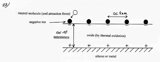
1) Surface ions
Some ions, uniformly spread over the surface, replace the metal grid of the first configuration. The gas molecules would be attracted by a high density electric field close to an ion. The distribution of the ions would be automatically done by repulsion of the ions among themselves. The ions could be produced by electronic emission from a cold cathode (which emits electrons with a weak electric field) into an electronegative gas ( a molecule which easily picks up a supplementary electron) such as SF6.
Advantages:
·A high field close to an ion (1,5 x 10⁹ V/m).
· The thinness of the dielectric ( 10 nm) and the static charge of the negative ions prevent a breakdown of the dielectric.
· One avoids the problems linked to the metallic grid, i.e :
- A too high field next to the metallic ridge which might ionize the neutral-gas molecule.
- Emission of ions from the metal of the grid which would come and “pollute” the dielectric surface by scattering away the positive charge first concentrated on the grid, which would progressively weaken the electric field in the holes of the grid.