The applications

are first of all those of the actual heat pump, with an interest highly increased by  the high coefficient of performance. Some other specific applications come from this high coefficient of performance, all these inventions coming to graft themselves on the basic process. It would become possible to cool the environment, for instance the water of a stream or a river, to deliver work, for instance electricity or to cool sea water to produce  both electricity and fresh water. It becomes also possible to consider thermoelectric generators which could advantageously replace the actual generators, as well as the generating units and even the batteries for particular use.


Traditional applications of the heat pumps
but whose interest would be enlarged by a high C.O.P.
  • Heating and air-conditioning of council estates or flats, hospitals, hotels, schools, auditoriums and offices.
  • Water heaters, heating for swimming pools, greenhouses, soil for mushrooms culture, water for fish breeding.
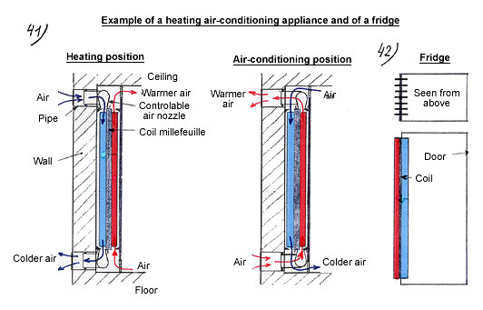
  • Fridges (see diagram below).
  • Refrigerators for preserved food and food industry, for the air-conditioning of port installations.

Heat recycling devices ( without external input of heat at the cold source)

  • Fur, meat, wood, paper, cereals (corn, barley) drying.
  • Evaporation for the concentration of aqueous solutions in food industry, paper manufacturing and chemical industry.
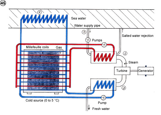
  • To remove salt from the sea.

Provided that the process be able to deliver a warm source up to 120°C

One can note a potential market in:

  • Oil refining
  • Paper making
  • Food industry
  • Alcohol distilling

Other applications linked to compactness, simplicity, absence of noise.

  • Small portable fridges
  • Air conditioned containers
  • Heating / air-conditioning appliance for individual lodging (diagram below).


Example of a heating – air conditioning appliance and of a fridge


SPECIFIC APPLICATIONS OF THE INVENTION

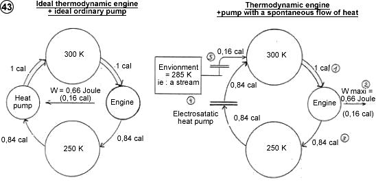
1)  Conversion-of-ambient-temperature-into-work Station (Thermodynamic station with a sole thermal source)

The principle consists in associating a heat pump to a thermodynamic engine in order to make it deliver more work than the pump consumes. the ambient temperature brawn into the environment ( ground water, river, lake, sea, atmosphere …) provides the necessary energy to deliver useful work. The thermodynamic engine works by draining off some heat from the warm source to the cold source (warm pipe and cold pipe), while at the same time, converting some of this heat into work, whereas the heat pump carries the heat “up” from the cold source to the warm source.

Such a system can only work with a heat pump whose C.O.P is superior to Carnot’s. Indeed, as long as the heat pumps were limited by Carnot’s C.O.P, the coupling of such a pump with a thermodynamic engine could, at the best, only reach to the reciprocal neutralization of their effects, the totality of the work delivered by the engine being consumed by the pump (see diagram below on the left).

But we would get the required effect if the C.O.P of the pump became superior to Carnot’s. In the case where there is no work to deliver at all at the pump, all the work delivered by the engine can be freed. This work would come from the conversion of the ambient temperature drawn into the environment (see diagram below on the right.)

Thermodynamic cycle (the temperatures are arbitrarily chosen).

(1) Given a calorie taken at the warm source by the evaporator of the engine.

(2) The engine transforms some of this calorie into work (0.16 calorie max.)

(3) The remaining part (0.84 calorie min.) is discharged by the condenser at the cold source.

(4) To maintain the temperature of the cold source the heat pump must take this quantity of heat back to the warm source. If the work to deliver at the pump is nil, this quantity of heat is transferred to the warm source, nothing more.

(5) In the end, the warm source has cooled down of 0.16 calorie, that is to say the quantity of heat converted into work. One can warm it up by taking some heat into the environment with an auxiliary heat pump since the environment is usually colder than the warm source in our case.

Working principle ( the station having been started) (see diagram 44)

(1) The work fluid, generally ammoniac arrives into the evaporator where it takes heat at the warm source. The warm fluid (in red) undergoes a cooling down of a few degrees ( the warm plates of the heat pump could play the role of evaporator. In the same way the cold plates could play the role of condenser).

(2) Ammonia vapor arrives into the turbine where it expands by delivering a work whose value depends on the difference of temperature between the warm source and the cold source.

(3) The vapor penetrates into the condenser where it yields heat at the cold source. The cold fluid (in blue) then undergoes a warming up. The ammonia now a liquid is pumped and compressed again, then a new cycle starts.

(4) To maintain the temperature of the cold source, the heat pump must take “up” again the heat drained by the engine. thanks to its high C.O.P, it can do it by using only a small part of the work delivered by the engine with the help of a generator connected to the engine. But we could also make it work with the electric-grid system if the work delivered by the station isn’t converted into electricity.

(5) The role of the auxiliary pump is to take some heat into the environment to introduce it at the warm source. It is this energy that will be converted into work. But one could also directly warm the cold source with the help of a simple thermal exchanger (see configuration on the page 25).

Available power

Each calorie taken into the environment is entirely converted into work. If it is a stream, each gram of water discharged and cooled of 1°C would provide 4.18 Joules (4.18 MW/m3/s). A station that would cool down of 1°C the water running in the river Rhine, would give on average 9196 MW ( average flow: 2200m3/s), the river Rhône: 7106 MW, the river Loire: 3300 MW, the river Seine: 1567 MW, the river Garonne: 836 MW.

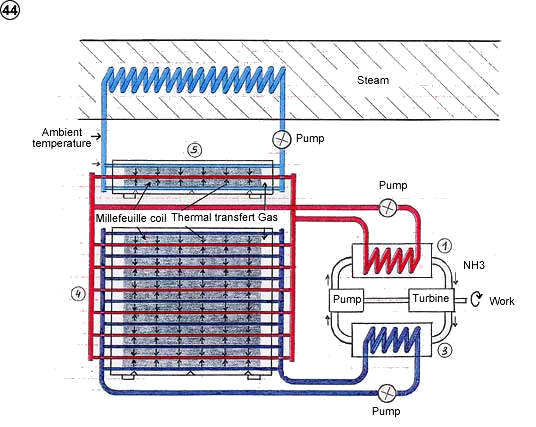
2)       House supplying power and fresh water with sea water

The principle is the same as in the configuration mentioned before, except that the work fluid used in the thermodynamic engine is now sea water, with production of fresh water at the condenser. This possibility has already been applied in the sea thermal energy ( Georges Claude’s process) but one had to have a warm source and a cold source at one’s disposal, the later being the deep cold water reservoir of the tropical seas ( about 5°C. See Ph. Marchand’s book: L’énergie thermique des mers, IFREMER edition), while the warm source is the surface water (20 to 25°C). In the actual case, the surface water is enough and all the seas can be suitable.

How it works

(1) Some of the water aimed at warming the cold source is diverted by a pump towards the evaporator where it is heated at the temperature of the warm source.

(2) Under the influence of heat and depression (the evaporator and the condenser are at 10 meters above the sea level) the water evaporates. To avoid the formation of salt into the evaporator, one introduces a bigger quantity of water than the one to evaporate in order to be able to evacuate the salt with the extra water.

(3) The steam goes through the turbine where it expands itself by delivering work. Then it penetrates into the condenser and liquefies into fresh water at the temperature of the cold source (between 0 and 5°C – under this temperature the water freezes).

(4) As in the configuration where one introduces only electricity, the system must be fed with heat taken into the environment to produce work. In the actual case, the sea water being only slightly warmer than the cold source, one can directly warm the cold source with the help of an ordinary thermal exchanger, which avoids the auxiliary heat pump.

3)      Thermoelectric generator

The principle consists in interposing a thermoelectric element between the warm and the cold plate of two close millefeuille-coils, the thermoelectric element replacing the turbine and the generator of the thermodynamic station. The alternated disposition of millefeuille-coils and thermoelectric elements allows a constant and homogenous circulation of the heat, as is shown on the diagram below. Indeed, contrarily to the thermodynamic station where the heat of two juxtaposed coils had to go towards the warm pipes, here the coils are all placed in the same direction so as the heat can circulate in the same direction. The thermoelectric elements leave the heat flow from the warm part to the cold part by converting a small part into electric power, while the coils take this heat backward from the cold part to the warm part. So, they recycle the heat which flows into the thermoelectric elements to integrally convert it into work (electricity).

How it works

§         Starting: With the help of a battery, one starts the millefeuille-coils. The warm plate of each coil warms up and the cold plate cools down. Meanwhile the heat starts flowing into the thermoelectric elements according to a more and more intense power which produces electricity.

§         The millefeuille-coils recycle the heat which flows into the thermoelectric elements but as some of it is converted into electricity, the system might cool down. Hence the introduction of metal plates welded to the thermal exchanger and stuck in the middle of each coil whose role is to feed the system with the ambient heat taken by the thermal exchanger. This heat can be brought by a fluid (air, water…) or by a burning gas, a radiance or by mere thermal transfer with a solid supporting the apparatus (ex: the ground).

Applications: generator for satellite, isolated resorts, beacon, buoy, meteorology, generating unit, battery for thermal engine, batteries…