Advantages – difficulties
This configuration, close to the reference pattern, aims at solving the point-effect problem that would occur by the ribs of a metallic grid. A very high electric field, of about 1010 V/m, could induce an auto-ionization of the neutral gas molecules, that is to say without collision with another particle, just because of the intensity of the electric field by the ribs. In the present case, the positive charge would be ingrown into the dielectric mass thanks to the grafting of donor atoms. These atoms would get ionized by the application of the electric field and the electrons would flow into the ultra-thin layer superficially grafted. The dose of donor atoms would be calculated so as the positive charge be not only located on surface like a metal, but grafted into the volume of the material in order to avoid the point effect.
About the risk of emission of positive ions from the grid which scatters the positive charge and progressively weakens the electric field in the holes of the grid, we may suppose that the use of a dielectric would be preferable to the one of a metal whose emission certainly comes from the ionization of the gas absorbed superficially. If, in spite of all that, the problem remains, a solution to re-establish the electric field in the holes of the grid would be to momentarily inverse the polarity of the process ( negative charge on the grid and positive charge under the dielectric). Another way would be that while the tension in the dielectric is suppressed, to periodically emit electrons on the whole surface of the dielectric to discharge the positive ions thanks to a cold cathode located on the inferior side of the thin plate.
About the risk of breakdown of the dielectric, the problem could be solved in the following way: we apply the voltage to the plate in the vacuum case. If a breakdown occur, a dark spot should appear and help us to locate the place where the breakdown occurred. It would then be necessary to clean the grid in this right place to isolate it from the conductive canal which took shape during the breakdown. The cleaning can be made with an ionic canon or a laser.
The dielectric rigidity will be all the higher as the holes of the grid and its thickness will be small because we will be able to reduce the thickness of the dielectric accordingly.
Besides, I have experimented a strategy at the L.C.I.E (Laboratoire Central des Industries Electriques in Paris) in order to increase the dielectric rigidity. It is based on the interfacial polarization. It consists in interposing a weak-resistivity insulation (1010 to 1014 W cm) between the metal of the cathode and the high-resistivity insulation destined to be laid under the grid, in this case, Parylene ( 1017Wcm). This strategy has the effect of nearly canceling the electric field in the weak-resistivity insulation, and by so doing, avoids any electronic injection in the Parylene because the cathode is now only submitted to a very weak electric field. This experiment demonstrates that with an equal electric field and an equal thickness of Parylene , we get a high reduction of the measured current, of about the half, but also a high increase of the dielectric rigidity of about 70%.
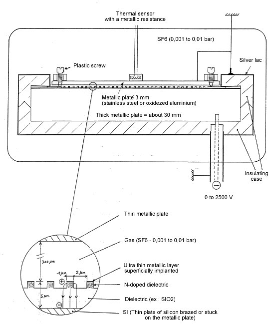
Thickness of the platesThe thick metallic plate (about 30mm) is the warm plate called electrostatic. Its thickness must allow an inertia of temperature that is to say a very weak warming which will facilitate the measurement of the cooling of the thin metallic plate (about 3mm).
It is preferable to measure the cooling of the thin plate to precisely enlighten the transfer of heat between both plates and this rather than the warming of the warm plate which could be interpreted in other different ways.
Role of the insulating caseIt is made of two half plastic lids jointed the one into the other, and covered with a thin silver lac linked to the nil-potential mass. It is destined to suppress all electric field out of the process, in order to avoid a breakdown in the gas between two parts away the one from the other and with different potentials.
Measurement of the coolingOnce the vacuum is established, we let the tension rise slowly, then once we get the required tension, we introduce the gas at 0.001 bar first. A cooling of the thin metallic plate must then be noticed, of about 1°C at 1250 V (250 KV/mm in Parylene and 500 KV/mm on surface) because one must take into account that the holes of the grid represent only the half of the whole surface.. The cooling will be proportional to the square of the electric field, consequently, we should have 4°C with a field of 500 KV/mm, 16°C with a field of 1000 KV/mm. We will make a note of this cooling at different moment after the introduction of the gas to know the cooling speed, then the power of thermal transfer, and then the equilibrium temperature when the transfer is cancelled.