Advantages – difficulties
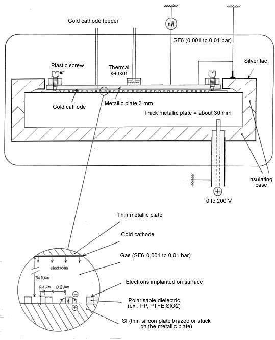
Some electrons are emitted from a cold cathode laid under the thin plate, and get grafted into a polarizable material such as PP, PTFE, or SIO2. By positively charging the thick plate and by grounding the thin plate, an electric field is created between the two plates and it is going to attract the electrons and provoke their implantation to a deepness of about 10 nanometers for a potential of 100 volts. The uniform repartition of the implanted electrons must avoid a too important concentration on the edges as well as a point effect.
Contrarily to the previous configuration, the ionic emission from the anode, if it takes place, wouldn’t imply the obligation of stopping the device anymore. One just have to make the cold cathode work and to re-implant the electrons. The dielectric layer becomes too thin for a breakdown to occur and the implanted electronic charge, which is static, also contributes to limit the risk.
The interest of this configuration will depend mainly on the difficulty to get the required charge ( 0.01 Coulomb minimum / m2). One of the reasons why this difficulty might occur is that some of the electrons are going to fall on the edges of the grid and skim its vertical sides, which might ionize the dielectric and the freed electrons would be immediately sucked in the vacuum towards the silicon surface because of the high electric field in this zone. In that case it would become impossible to increase the charge of the electret as soon as the electric field in the holes of the grid reaches a certain level. The most obvious solution consists in reducing the energy of the implanted electrons as much as possible because it is from this energy that depends the power of ionization of the dielectric by the electrons. Another solution would be, not to implant electrons but negative ions on the surface of a micro porous dielectric. The ions power of ionization is a lot weaker, at a low energy, than the electron’s.
The charge control
The charge level of the electret will be controlled thanks to the tension switch and a nano or pico-ammeter. During the charging operation of the electret, the necessary tension to accelerate the electrons to implant is set. The charge level is estimated by the measurement of the time elapsed . If we want to know the exact level, we stop the feeder of the cold cathode then we let the tension drop slowly until the potential at the level of the implanted zone is cancelled and then becomes negative. At this moment, the thin metallic plate must start to charge positively and some unstable electrons in the electret must go back towards the thin plate, what must be detected with the nano or pico ammeter. At this moment, the tension control will indicate the tension level in the electret and consequently its charge level and the value of the electric field in the holes of the grid.
Thickness of the plates- insulating case- measurement of the cooling: see 1st possibility .
Electric power consumed
It will essentially depends on the stability of the implanted charge. The life span of a conventional electret is about of a century which means that it would have to be re-charged every century. But in the actual case, the required charge level would be, at the minimum, ten times higher than the most highly-charged-conventional electrets, and to compensate one can expect a considerable diminution of the stability. Let us imagine the very unfavorable case in which the life span would fall to 10 seconds. It would then be necessary to re-charge the electret every ten second, which induces a constant emission current of about 10-3 ampere/m2. With a potential of 200 volts, we would then get a consumed power of 0.2 Watt/m2, which is still negligible compared to the power of thermal transfer to expect.